Tutorial 4: Continuous 3-Span Bridge with NU-1600 Girders (Metric Units) (LRFD) Hand Calculation Selected Items
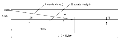
This design example is an example of continuous three-span bridge with NU-1600 girders. Diagrams and hand calculations are included in this section. It demonstrates the design of 30000, 33000, and 30000 mm NU-1600 beam bridge, as shown in Figure 9, Component Forces of Total Prestress Force, on page 8.
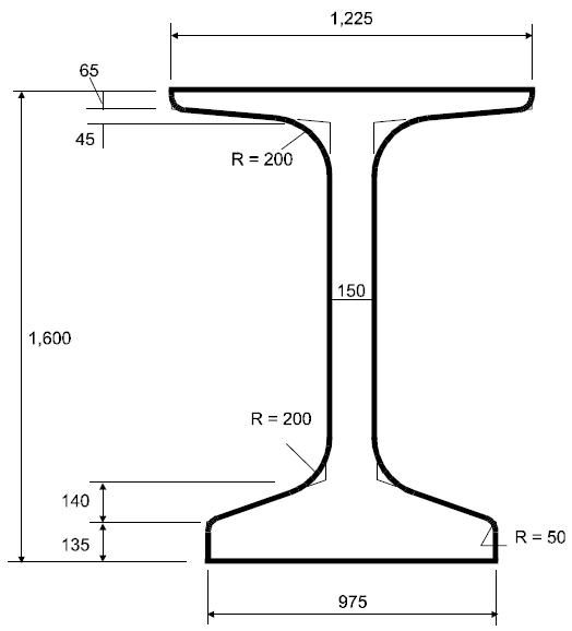
This example illustrates in detail the design of a typical interior beam of the center span at the critical sections in positive flexure, negative flexure, shear, and deflection due to prestress, dead loads, and live loads. The superstructure consists of four NU-1600 beams spaced at 3600 mm centers, as shown in Figure 12, Bridge Cross Section, on page 18. Beams are designed to act compositely with the 200 mm cast-in-place concrete slab to resist all superimposed dead loads, live loads and impact. A 10 mm wearing surface is considered to be an integral part of the 200 mm slab. Design live load will be AASHTO LRFD HL-93. The design will be carried out in accordance with AASHTO LRFD Bridge Design Specifications, Third Edition, 2004.